
Slicing 3D Objects for a Laser Cutter with OpenSCAD
2017-09-29
Recently, my makerspace got a new laser cutter that can fit 4x2 foot plywood sheets. This means I can redo our arcade’s control panel with a design in OpenSCAD. Here’s the mockup:
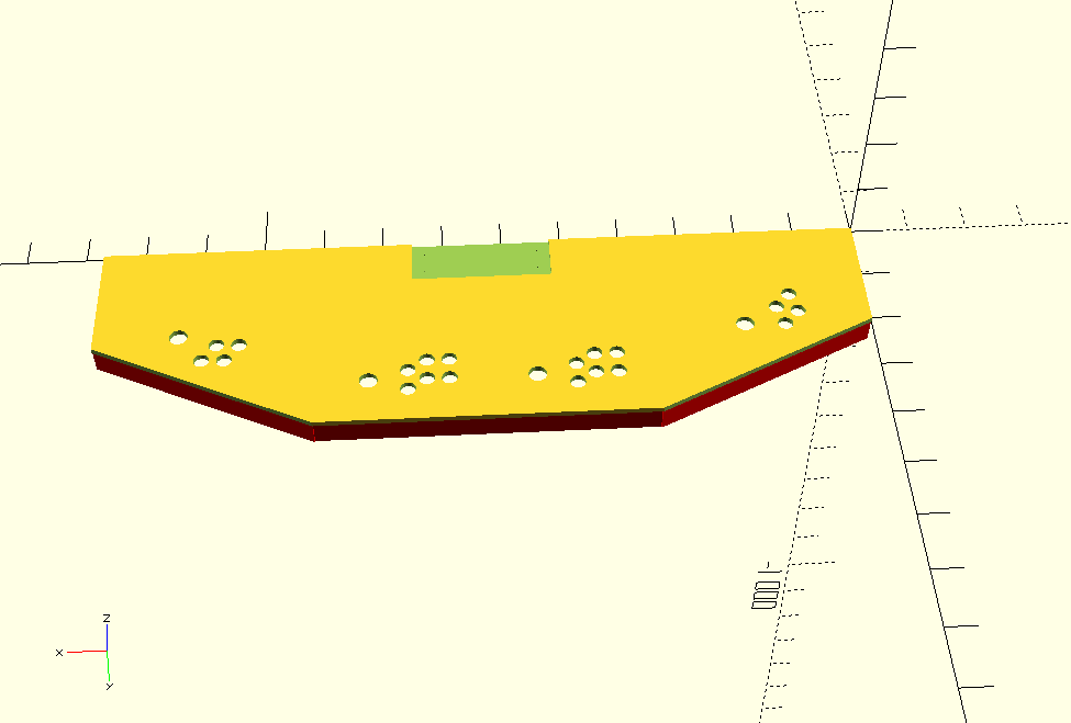
The design is based on the old X-Men 6-player cabinet, though the final build got cut down to 4-players for space reasons. The red areas you see on the bottom are keepout sections for the structure underneath. There’s also a cutout in back, which is for a built-in keyboard. It’s 3/8 inch thick, and intended to be made from two layers of 1/8 inch plywood plus 1/8 inch acrylic on top.
Now, how do you go from an OpenSCAD file to a laser cutter?
In theory, you can have OpenSCAD generate an STL file, and then import that into a 3D printer slicer. A slicer’s job is to take a 3D model, break it into 2D slices, and then generate the printer head’s path for each slice. So you might think that you can set the slicer to have a layer height of 1/8 inch, and then have it output some kind of vector file format for each slice. Slic3r does indeed have an SVG output, which gives you hope.
Your hope will soon be dashed as you run into impedance mismatches. First, Slic3r wants the nozzle diameter to be larger than the layer height. We’re not going to be dealing with a physical nozzle here, but we have to set it to a ridiculous size (like 10mm) just to make Slic3r happy. Once we get past that, we get our SVG output in a single file with multiple layers. Slic3r’s SVG output is meant for resin 3D printers, and isn’t going to work well for laser cutters. What we want is one file per layer with simple paths, not filled-in.
It turns out we can hack our own slicer with OpenSCAD’s projection() command, combined with importing an STL. It works like this:
projection( cut = true )
    translate( v = [ 0, 0, -0.1 ] )
        import( "arcade_control_panel.stl" );
The translate() brings the object’s Z coord down by -0.1mm. The projection() command then creates a 2D slice of whatever intersects at Z axis zero. Note that you need the cut = true here. Without it, OpenSCAD creates the projection as a kind of shadow of the entire object, rather than whatever is on the Z axis.
That gets us a vector image like this:
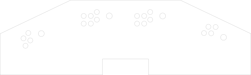
If we loaded the code above into OpenSCAD, compiled it, and exported to a vector file like SVG or DXF, we would get the slice of the 0.1 layer. Then we’d have to do -0.1 - 3.175 (3.175mm is about 1/8 inch), compile and export, and then again for the third layer. This is too much manual effort, even for just the 3 layers I need for the control panel. I would never want to do it for something like a terrain piece.
Fortunately, OpenSCAD has a command line interface for compiling and exporting models. What we can do, then, is programmatically create the OpenSCAD projection code, run the command line, and get each layer in turn.
Which is exactly what Laser Slicer does. Here’s how to run it:
$ python laser_slicer.py --input arcade_control_panel.stl --end-height 7 --start-height 0.1 --layer-height 3.175
Input file: arcade_control_panel.stl
Output type: dxf
Start slicing height: 0.1
End slicing height: 7.0
Layer height: 3.175

==========

Creating layer 1 at height 0.1
    Outputting to arcade_control_panel.stl_1.dxf
Creating layer 2 at height 3.275
    Outputting to arcade_control_panel.stl_2.dxf
Creating layer 3 at height 6.45
    Outputting to arcade_control_panel.stl_3.dxf
We put in a start height of 0.1 (you might get weird results if you try to start with zero), then go up 3.175mm each step, ending whenever we go above 7mm. It then generates 3 dxf files, one for each layer. It’s probably slower per layer than 3D printer slicers, but since the layers are thicker, it doesn’t need to generate as many of them.
All code on Github now.